===================================
Project Name: Thunderbolt
Project Domain: High Voltage Physics
===================================
Goal: To create a full scale Tesla Coil with that produces at least 6in sparks aka “artificial lightning”.
Current Status: Project was a success, with a complete full scale, full power test on Friday, July 15, 2011!
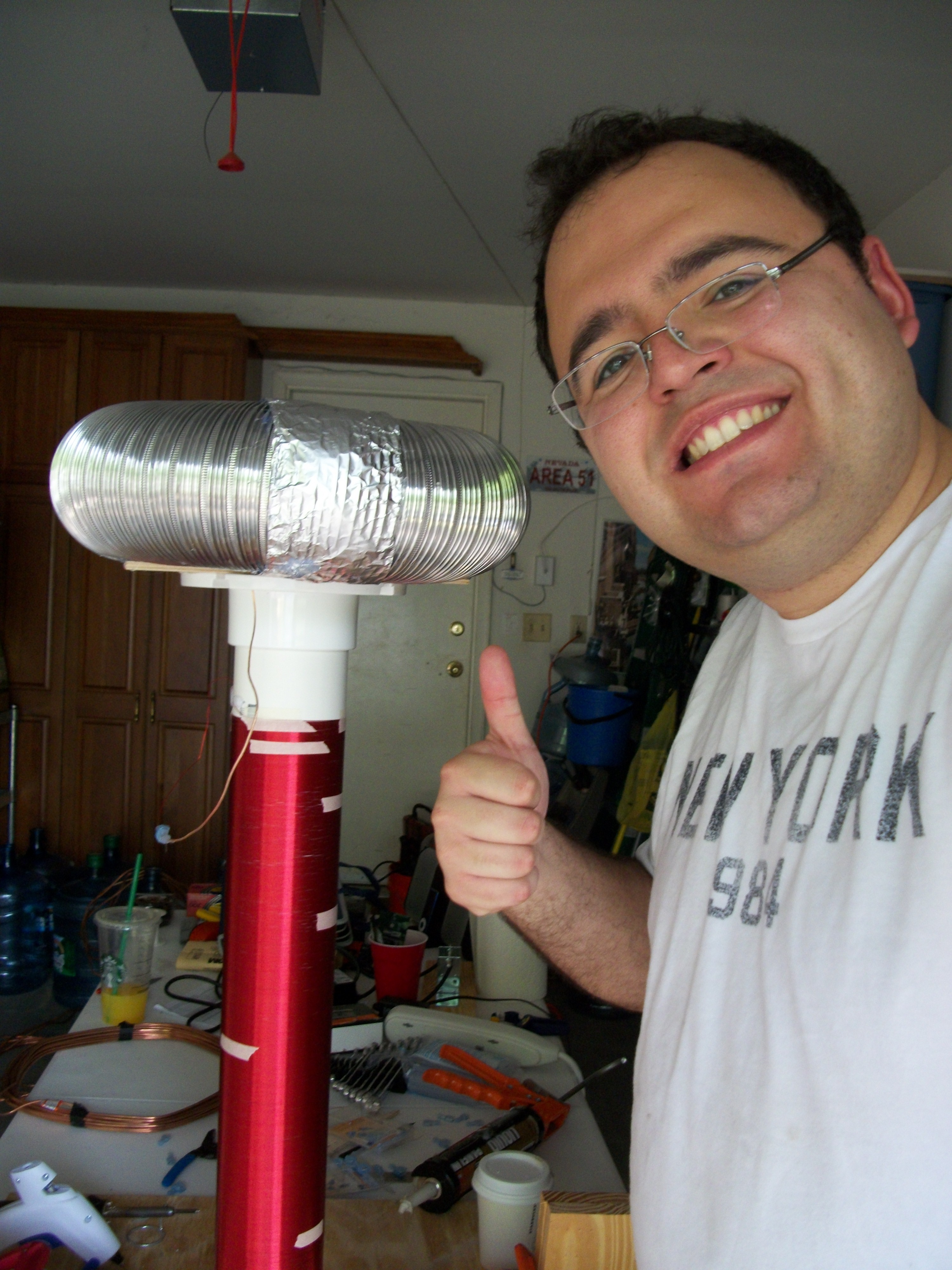
Me and My Tesla Coil:
Tesla Coils and Nikola Tesla: Check out WikiPedia for more information on what a Tesla Coil is and the history about them. Also, please read about their inventor, definitely one of the most important inventors throughout Human History, Nikola Tesla.
My interest in Tesla Coils started when I first visited Liberty Science Center as a child. They had a fully working Tesla Coil on display and would run demos, creating Artificial Lightning at will with the flip of a switch.
Ever since then I wanted to build and possess my very own Tesla Coil.
When I was younger I never attempted it because of the huge voltages involved, as well as a general lack of funding. My 2011 build cost approximately $1000.00 in parts and materials. I could probably build one for less now, having mastered a build, but a lot of my first Tesla Coil build was trial and error and there was a bunch of failed parts and ideas, which increased the total cost of completing a working Tesla Coil.
Here’s the Part List of my Thunderbolt Tesla Coil:
- 800 Feet of 24 AWG Magnet Wire
- 12,000V, 30MA Neon Sign Transformer (Purchased used from eBay) non-Fault Tolerant (this is important, a Fault Tolerant Transformer will cause your Tesla Coil not to work).
- 48X 0.49nF 20,000V Capacitors (I purchased 200 of these for about a dollar a piece off eBay. They are normally used in High Frequency Pulse Lasers.)
- 30 feet of 12 gauge solid copper wire (bare).
- 3in diameter, 24in length of PVC Pipe.
- 2X matching 3in PVC flange
- 2X 24x24in plywood board
- 16in 1×4 Wood Plank
- 2X 2in wide Steel brackets
- 2X 3in screws with matching washers and nuts.
- Line Filter to protect the house mains.
- 100 feet of 14 gauge insulated copper wire
- Erector Set for building metal frames for Capacitor Tank.
- Aluminum Dryer Vent Flex Hose.
- Various bits of 2×4 Wood for standoffs, etc.
- Various screws for mounting everything
- Various cuts of thin plywood for primary coil mounting.
- Liquid Nails glue for mounting parts that cannot be held together by conductive material such as screws.
Circuit Diagram:
Special thanks to the Tesla Coil Wikipedia Article for supplying the Circuit Diagram, and specifically the creator: Wikipedia User: Omegatron.
Creating the Spark:
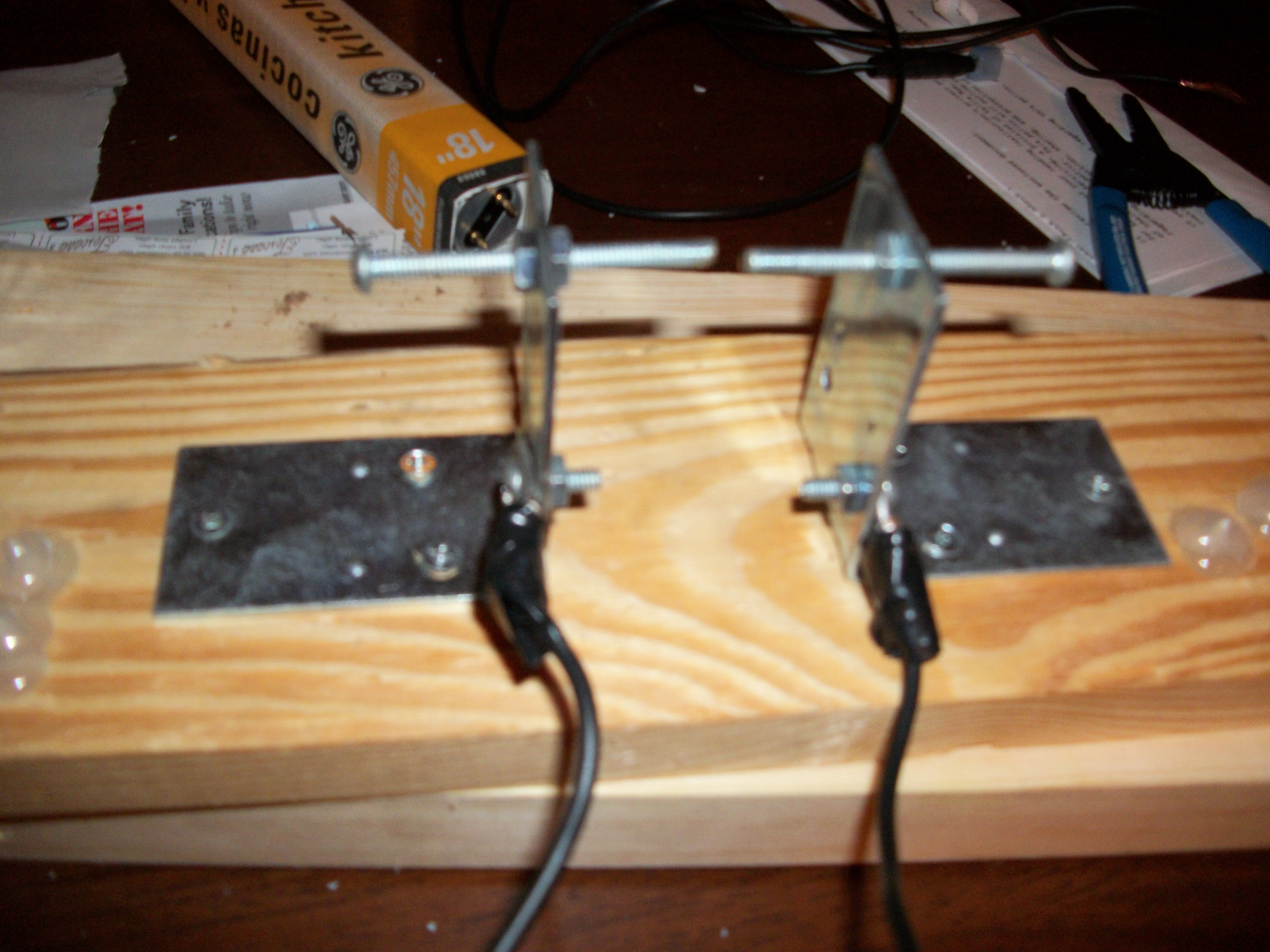
I used the two 2in steel brackets, and the 3in screws to create a static spark gap. It’s not the most efficient spark gap for Tesla Coils these days, but it’s the easiest to build and if you add a PVC pipe to cover the gap and connect a high power vacuum like a shop vac/wet-dry vac you can create a so-called “sucker spark gap” which will increase the efficiency of the Spark Gap. However, even without the Vacuum enhancement the static spark gap still works well for creating 6in – 12in arcs and a wireless energy field that will light up a 18in fluorescent tube 5-6 feet away from the Tesla Coil.
Here’s the fully constructed Spark Gap. I did re-align it, as you can see in this picture the screws are not facing each other perfectly square.
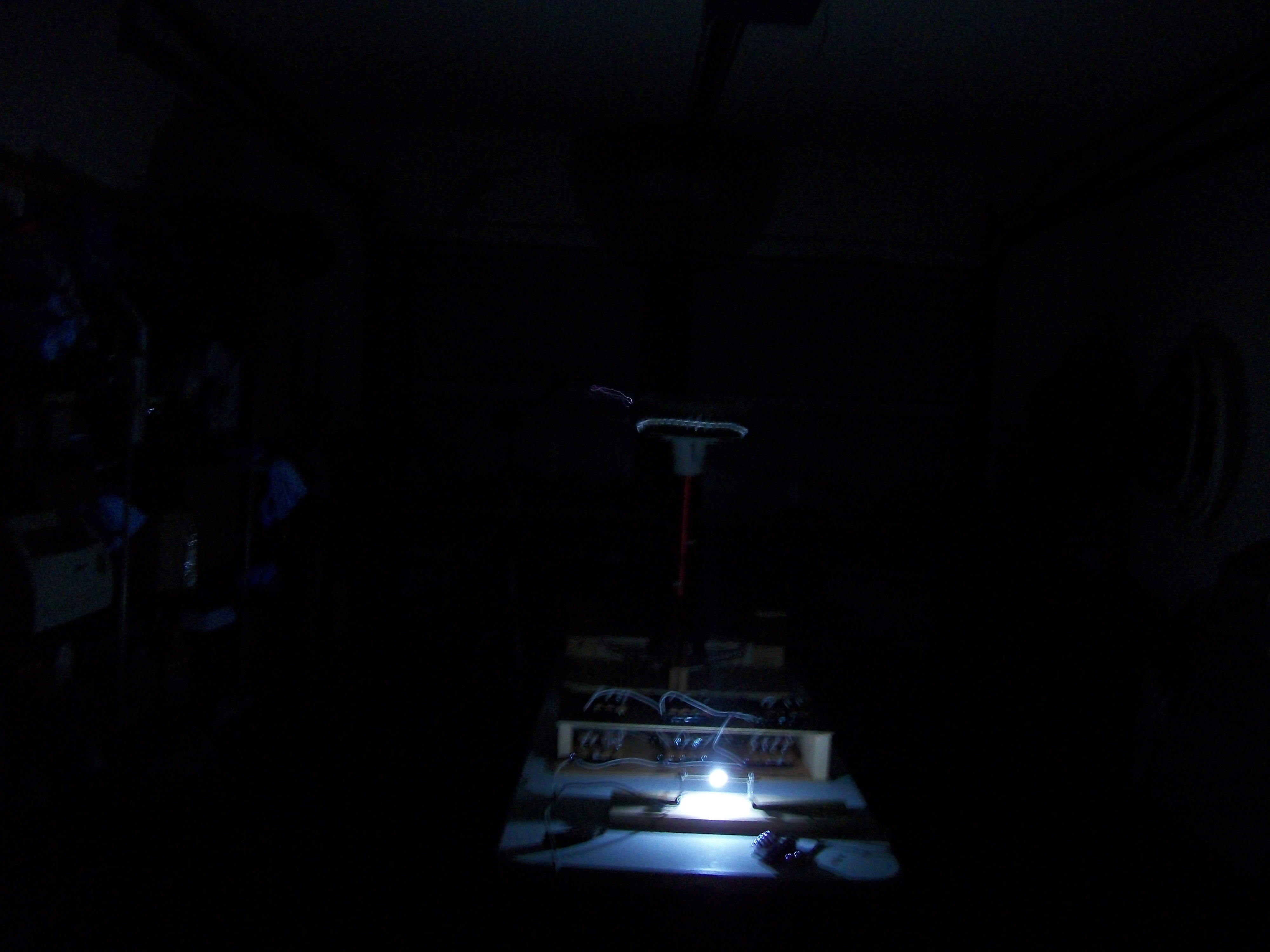
Here’s a picture of the complete spark gap in operation (the full Tesla Coil setup is pictured and visible in the background):
Here’s a test of the completed Spark Gap on my dinning room table, with the gap connected directly to the Neon Sign Transformer, this is for fine tuning of the gap. You need to ensure it can arc with the Transformer connected alone to prevent a full short circuit:
Check out this video of the spark gap in operation when connected to the Tesla Coil. What you will notice is that the spark is of much greater size, brightest and overall power than the video of the spark gap simply connected directly to the Neon Sign Transformer which I tested on my dinning room table:
Creating the Capacitor Tank:
From a capacitance standpoint, the value is quite low compared to say an LED flasher or something like that, it’s in the nano-farad range. However you need extremely high voltage and the capacitors need to be able to withstand high frequency charging-discharging cycles.
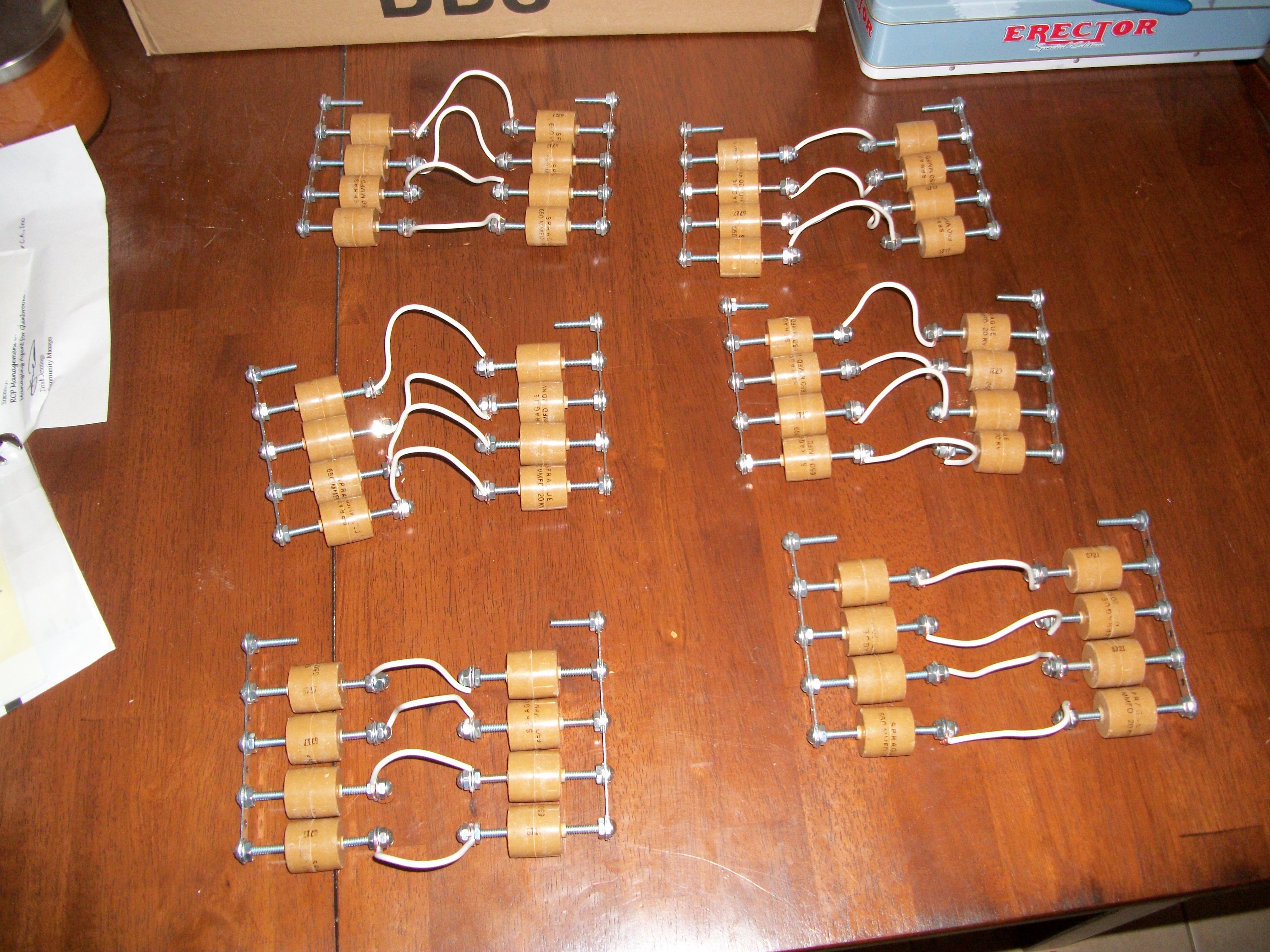
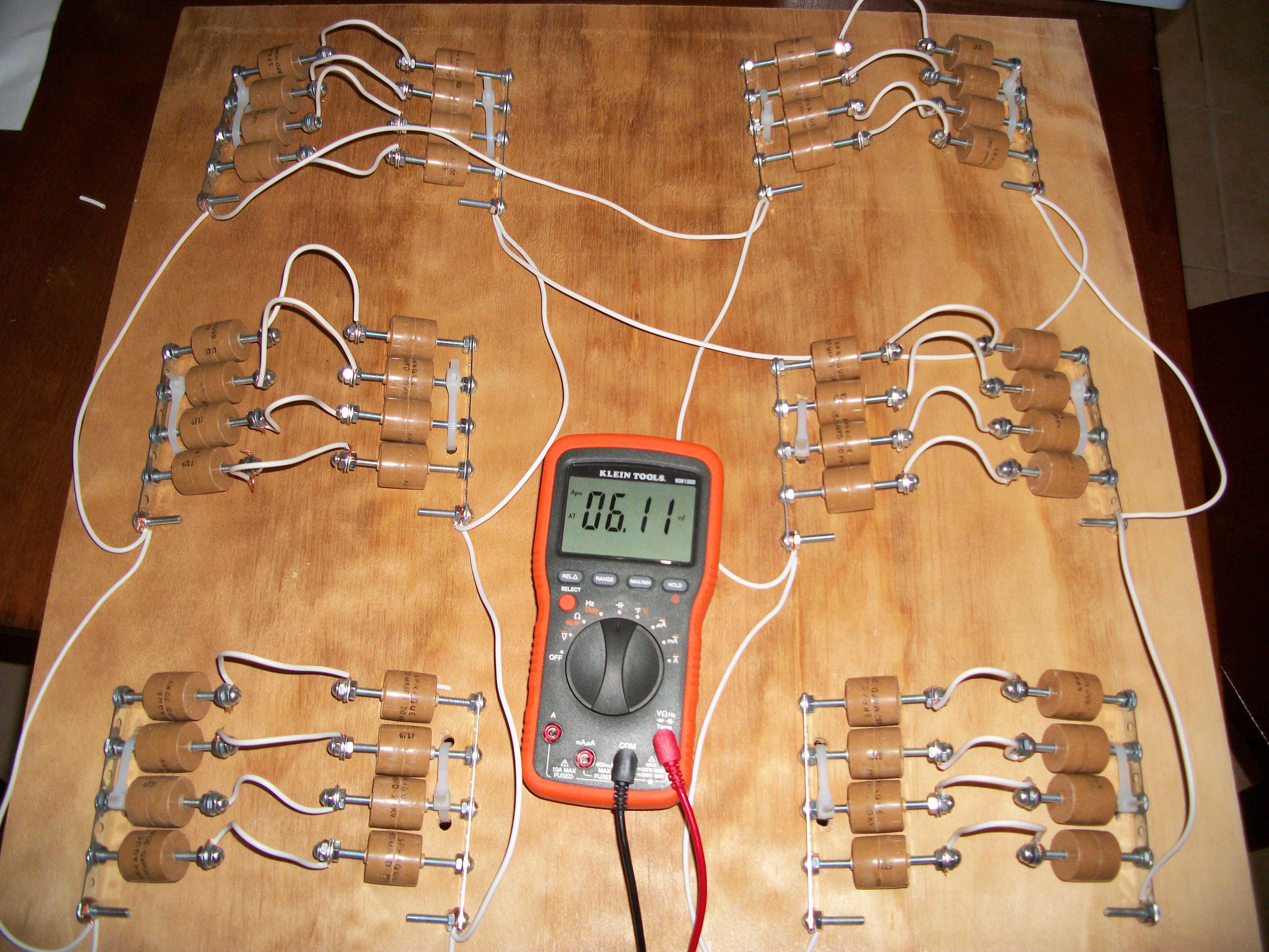
I used 48 of my 0.49nF Pulse Capacitors in the following layout:
2 capacitors in series connected in banks of 4 of these pairs in Parallel, for a total of 8 capacitors per rack created out of erector set pieces. The banks are pictured here:
I then connected these of these banks in parallel with duplicate banks totalling 6-banks of 8 capacitors giving a total of 48 capacitors in this matrix configuration. This matrix of serial and parallel capacitors gives a total measured capacitance of between 6.11 and 5.95 nano-farads by my multi-meter.
Here’s the completely Assembled Capacitor “Tank”:
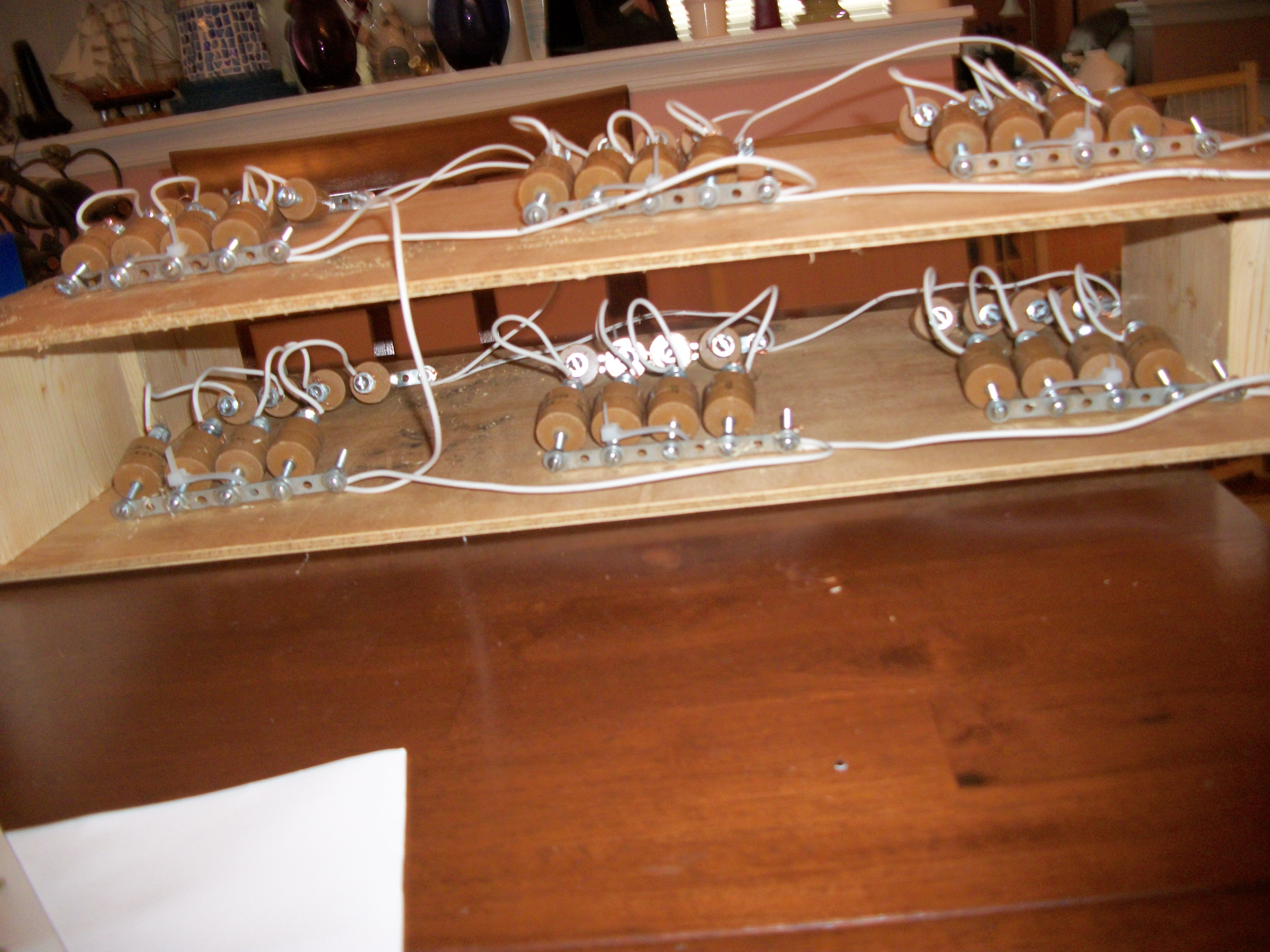
This physical layout cause arcs between the banks which were in parallel, plus the wires would arc right threw the insulator, so I refactored it into a double stacked layout:
Assembling the Secondary Coil:
It took me around 4 hours straight to wound the 800 feet of 24 gauge Magnet wire around the 3in PVC. 800 feet wound over the 9.43 in circumference over the PVC pipe gives you a little over 1000 winds. This is perfect, because my goal was a primary to secondary coil ratio of 1:100. That is 1 turn of the primary to 100 turns of the secondary.
The secondary itself is the nice upright red magnet wire most people associate with Tesla Coils. It usually has a tubular or spherical terminal at the top where the discharges occur.
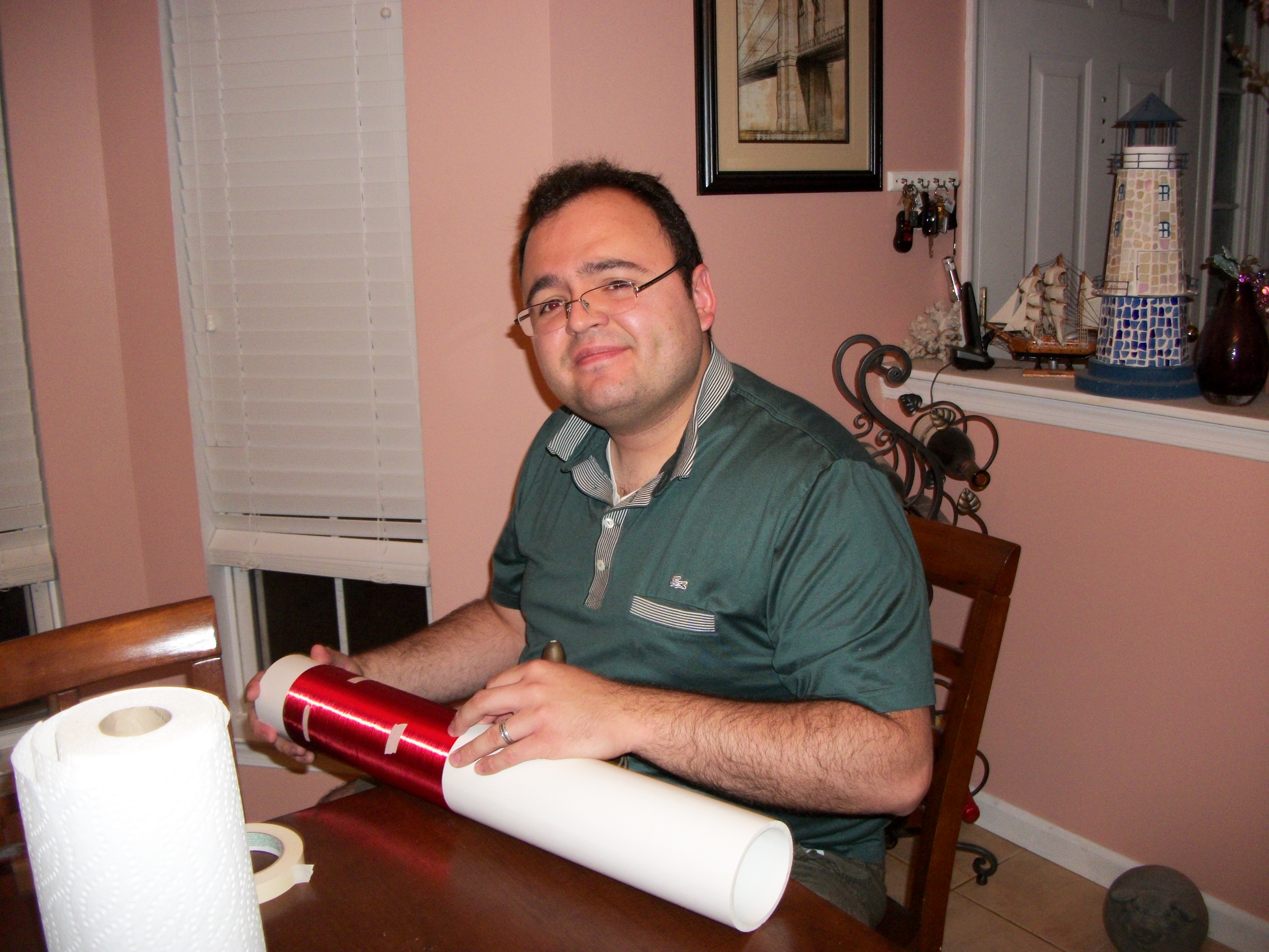
Here’s me, winding the secondary coil:
What you need to try to do is not have any overlaps in your coil. a few here and there doesn’t hurt the result, I found however. But take your time, otherwise it’s a waste.
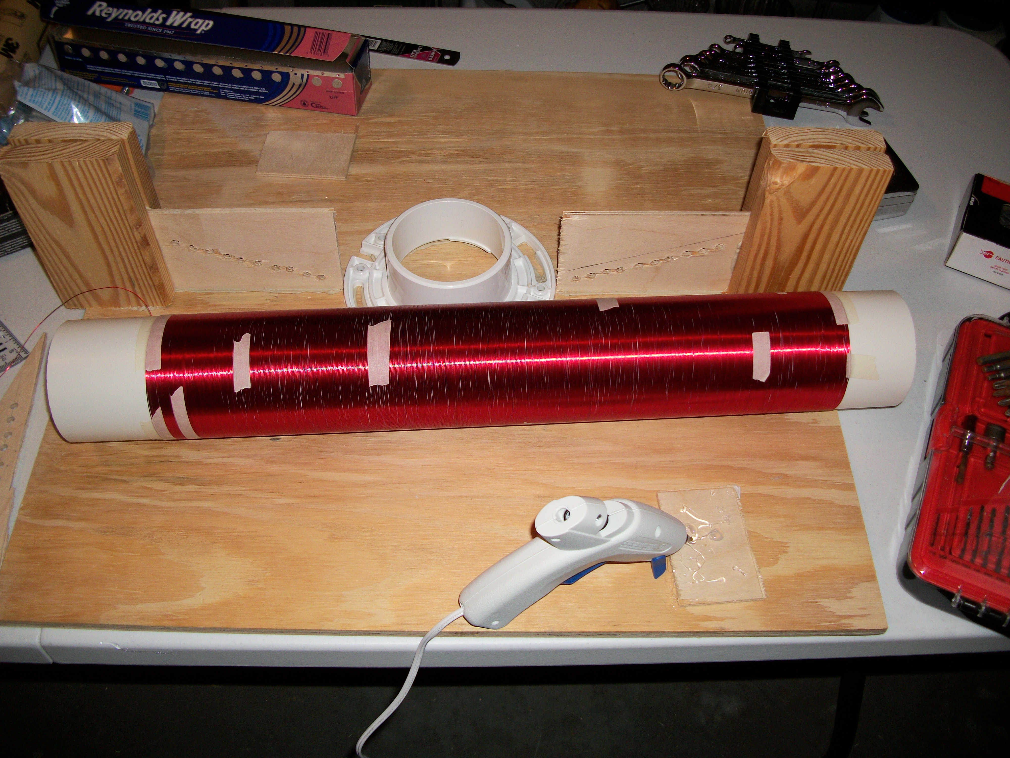
Here’s the completed secondary coil without terminal:
I mentioned at the top of the secondary coil you need a spherical or tubular terminal.
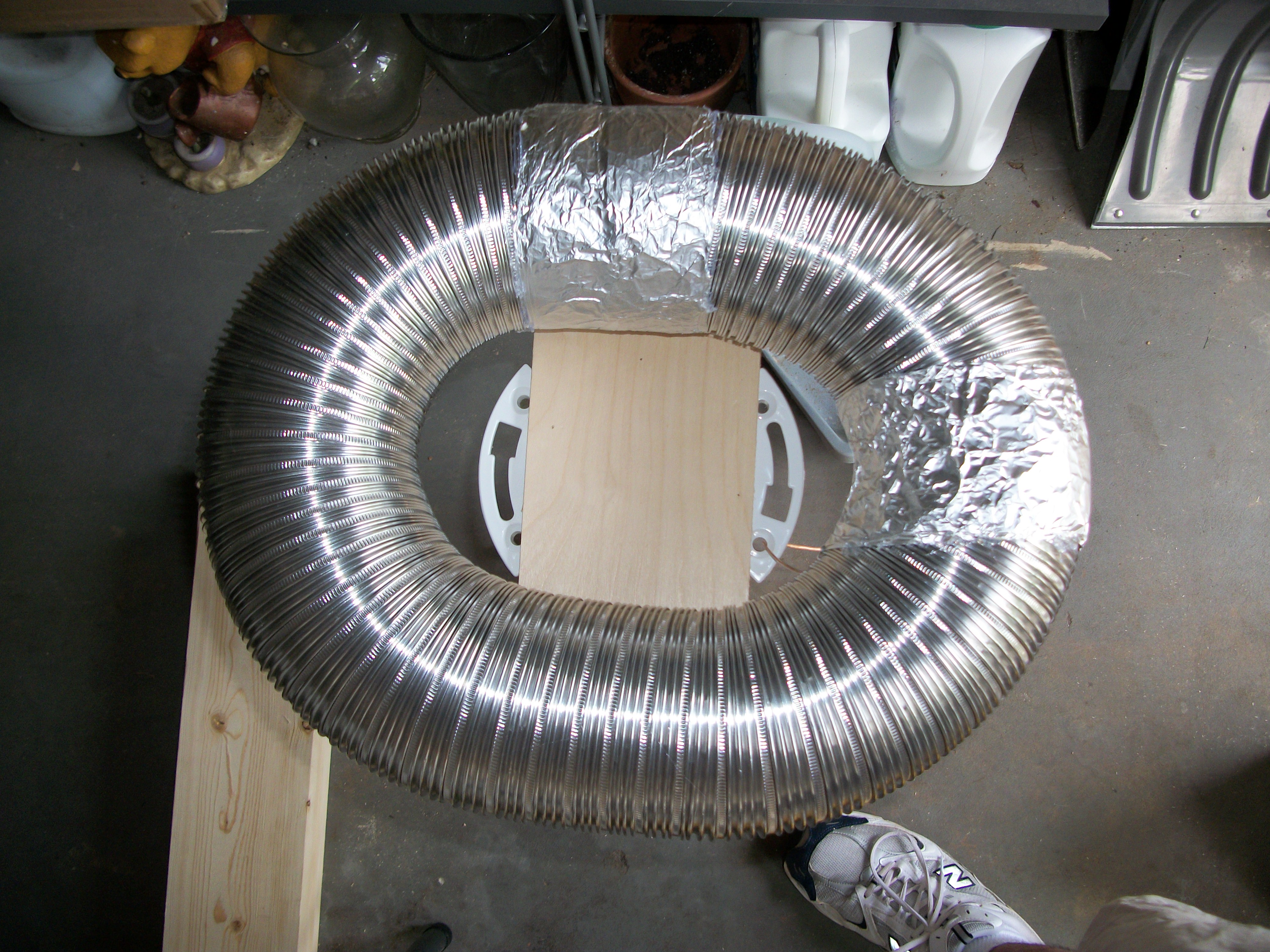
I used 3in diameter Aluminum Dryer Vent Flex Hose to create a circular tube at the top of my secondary coil.
Here’s a picture of the terminal:
As you can see I used Aluminum foil to close off any gaps in the flex hose, and the shape is more of an oval. I also used Liquid Nails glue to fasten the tube down to a piece of wood, which I then fasten to one of the PVC flanges, so that I can connect easily to the top end of my secondary coil.
I spent a lot of time thinking about how to make this entire setup modular, so I could transport it from my house to my mom’s and friend’s houses for demonstrations. The flanges worked great for this purpose.
Here’s the completed secondary coil setup with the base board, I used the second PVC flange to connect the secondary coil to the plywood board, again using liquid nails, as I didn’t want any conductive materials where I could have stray arc hitting the structure.
Creating the Primary Coil:
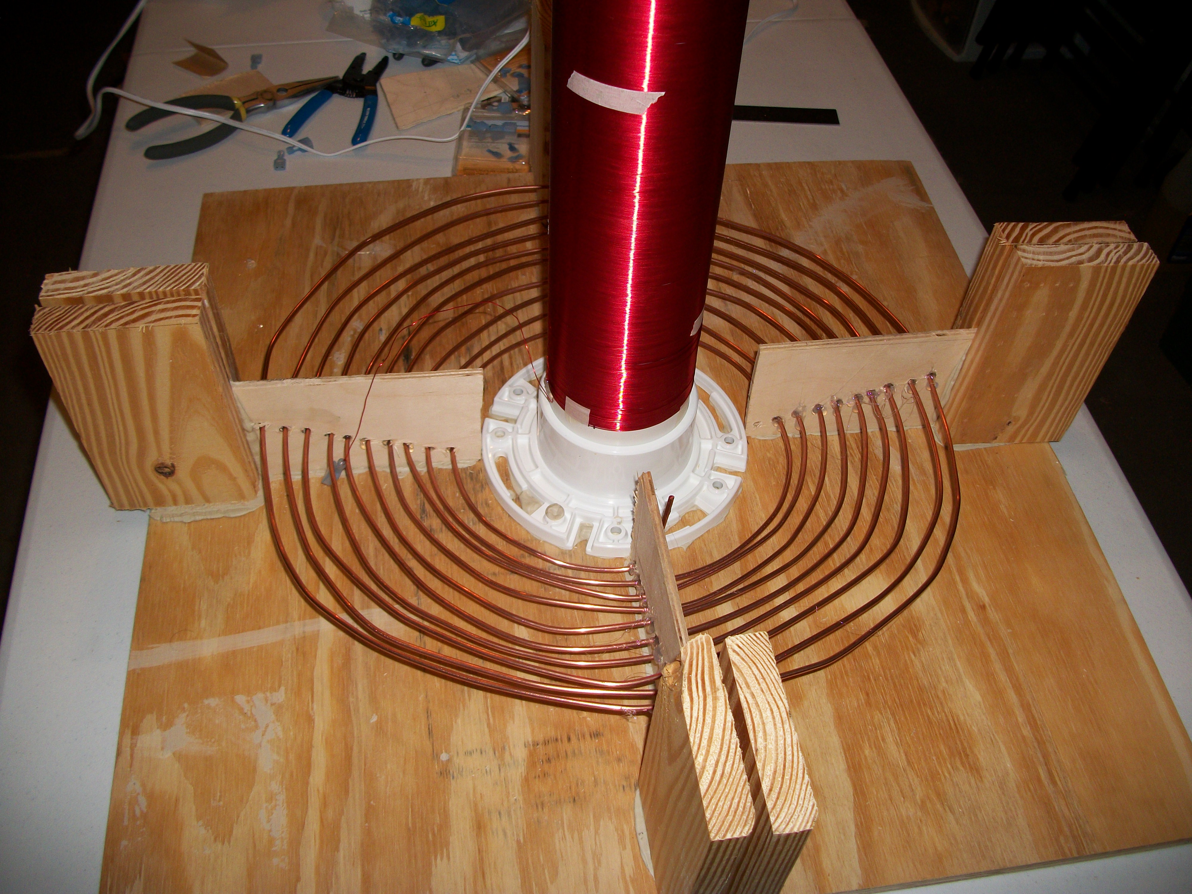
Although the primary coil only has 10 turns, it was more challenging to build for me than the secondary coil. I went through a few iterations before getting it right.
I used the the 12 gauge solid bare copper wire to create a secondary coil.
I eventually added one more turn of this wire to create a strike rail, which is connected right to ground to ensure there is no arc from the secondary to the primary, which would destroy the entire coil. The strike rail, is simply another turn of copper wire at the very top of the primary coil structure, which is importantly not a complete circle, it needs to be left opened, and it has one connection straight to true ground (the Earth).
Other then this you just need to connect everything up as shown in the circuit diagram above.
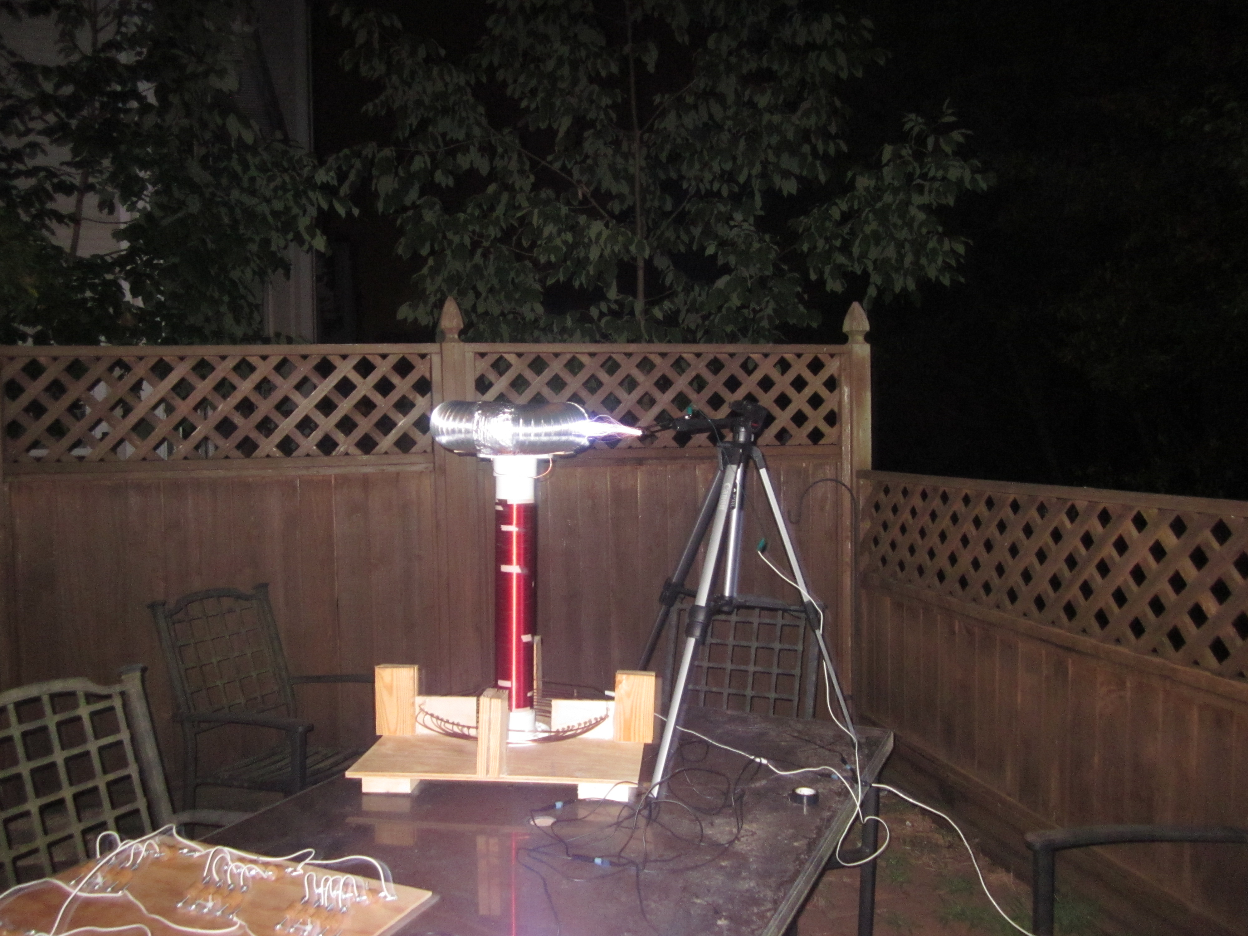
Here’s some photos of the Tesla Coil completed and operating as well as some video:
The Tesla Coil Operating in my backyard. The target object is a steel wrench on a camera tri-pod:
Here’s a video of me holding a 18in fluorescent bulb, acting as human ground, it proves my Tesla Coil is capable of Wireless Energy Transmission:
Wireless Electricity works! And yes, my Tesla Coil produces it!
Here’s a video of the Tesla Coil just striking a grounded target, the camera is directly below the coil, so it’s a great view of the lightning:
This is a head on view of the lightning. It’s a pretty interesting angle:
One of the first Full Power Tests:
For more videos please check out the following from the Ilardi.com Tesla Coil Page.
I hope this post was fun and interesting. I would really appreciate your comments!
Just Another Stream of Random Bits… – Robert C. Ilardi


Pingback: Singleton and Factories of Singleton | Enterprise Programmer